Basic solar wiring diagram

Basic solar wiring diagram
Wiring solar panels together
Wiring solar panels together, also called stringing, requires an understanding of how different configurations affect the solar array’s performance.
Voltage that exceeds what the inverter allows will limit production and possibly even the inverter’s life. Too little voltage, and the solar system won’t perform to expectations, as the inverter won’t work until “start voltage” kicks in. Shaded cells can also impact voltage. Growing foliage, nearby construction of tall buildings, chimneys or protruding pipes can all cause shade over panels, so you need to keep that in mind.
Solar panel wire types
Before you can create an electrical circuit, you need to settle on the appropriate solar system wires. This will enable the current to flow in the circuit to the inverter, which will transform the DC power to AC. Before deploying any solar PV system, check your local electrical codes, which regulate electrical installations in your area. Also, note: the National Electrical Code (NEC) prohibits using regular cables in your solar panel installation.
You need solar panel cables and wires designed specifically for the job at hand. Panel-wiring cable resists high-temperatures, flames, UV rays and moisture. You’ll also find that cables for solar panel array wiring last much longer than regular cables – between 25 and 30 years.
There are two types of wires:
A single wire is obvious – just one wire – while a stranded wire is multi-stranded. Stranded solar wires are larger than single wires. The current typically flows on the external part of the wire, which means stranded wires’ conductivity is better, as there’s more wire surface. They’re also flexible and durable – exactly what you want for wiring multiple solar panels and their components. Multi-stranded wires will also ensure reliable connections.
Minimising voltage drop
You’ll need different wires to connect:
Solar panels to the main inverter
Inverter to the batteries
The batteries to the battery bank and/or the inverter directly to the electric grid
When current flows through an electrical circuit, some voltage loss, called voltage drop, will occur due to resistance in the wires. This voltage drop reduces the solar array’s production and the longer the wire run, the more resistance. If you’re designing a PV system, give consideration to solar power wiring. Keep voltage drop to a minimum so that your array performs as close as possible to its peak rated output. Industry best practice considers voltage drop at 3% or less as acceptable, though you should aim for below 2% if it’s not too impractical.
To reduce the voltage drop in grid systems:
Minimise the length of the solar system wiring run.
Be strategic in the inverter placement. AC wiring from the inverter to service panel is often more vulnerable to voltage drop than high voltage DC wiring that run from the panels to the inverter or controller. Battery storage systems should be within 20-30 feet, and the charge controller should be mounted within a yard or metre of the batteries. If the DC voltage from the solar array is:
Higher than the utility service panel: install the inverter closer to the utility service panel.
Lower than the utility service panel: install the inverter closer to the solar array.
Use a larger wire size. The bigger the wire, the less resistance.
Design your system with higher voltage, which will also reduce resistance.
Solar panel wiring: series vs parallel
Are solar panels wired in series or parallel? That depends on what you’re trying to achieve. Wiring solar panels in series increases the array’s voltage while keeping the amperage the same. Wiring solar panels in parallel increases the amperage but keeps the voltage the same.
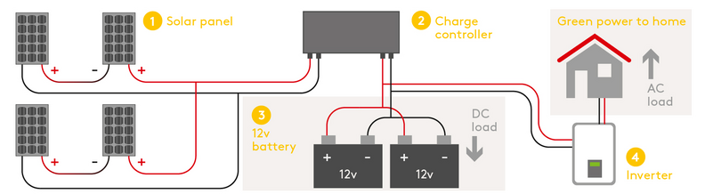
Basic solar wiring diagram
This solar system wiring diagram depicts an off-grid scenario where the solar panels are series wired. Grid-tied solar systems don’t need batteries and therefore, don’t need charge controllers, which monitor the current. The purpose of the charge controller is to ensure the batteries don’t over charge.
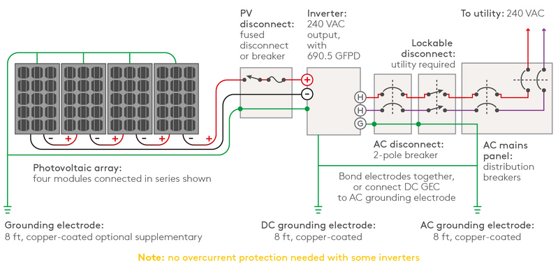
On-grid solar panel wiring diagram
In this PV system wiring diagram, the panels are series wired. On-grid systems need DC and AC disconnects in case power has to be shut off immediately.
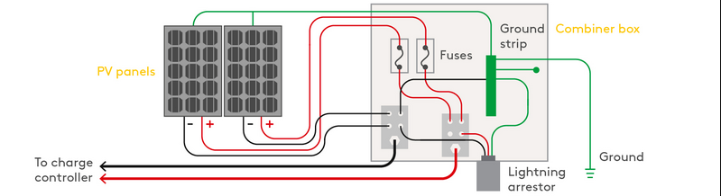
Solar combiner box wiring diagram
Solar panel combiner boxes are commonly used to combine solar panels into a bus. Essentially, these are junction boxes designed for the wiring used in PV systems. Large systems rely on combiners, but they’re helpful in small PV systems, enabling easier wiring and monitoring.
Relevant Products